The purpose of this article is to give an overview of how a Serial Servo Controller (SSC) works and to describe common interfaces. These servo motion controllers are used in many special effects, haunted houses, and other animatronic themed environments. Visit our Projects page for examples of several animatronic projects. Though we have taken steps to assure the quality of information here, Brookshire Software, LLC makes no guarantees about the information presented here. Brookshire Software, LLC cannot be held liable or accountable for any use or misuse of the provided information.
VSA supports many additional SSC's, as does the RAPU.
The MiniSSC II
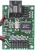
An SSC is a device used to control several servos from a PC across a serial or USB line. Although no longer available, the MiniSSC II protocol is still widely supported by many devices. The MiniSSC accepted formatted data from the PC and converted it into PWM signals for the servos.
Interface
MiniSSC compatible devices require three bytes to command one servo to a position. First, a SYNC byte must be sent indicating the start of a sequence. The SYNC byte is 255 (or 0xFF) and it always represents a new sequence. Next, the SERVO byte is sent. The SERVO byte indicates which servo needs to be moved (it cannot be 255). Finally, the POSITION byte is sent which tells the MiniSSC where to move this servo (it cannot be 255).
[ SYNC ] [ SERVO ] [POSITION ]
For example, sending "255, 1, 127" would move servo #1 to position 127 (the center point).
The SSC command architecture is simple enough, but consider this: if your robot has 16 servos and runs for a period of just 3 minutes, you will need as many as 86,400 commands -- 259,200 bytes of data. Click here to learn how VSA can handle the data in the background and create the illusion of a variable speed servo.
Timing
Notice that each command sequence requires 3 bytes, or 24 bits, of data. At 9600 bps (bits/second), MiniSSC compatible devices can process 400 commands/second (or a command every 2.5mS). If there are 8 servos on each device, each servo can receive 50 commands/second (or every 20mS).
Timing is by far the greatest challenge for any animator. Action must occur at just the right times at just the right speeds or the end result is simply poor. Even if you spend hundreds of man hours perfecting your actions on one machine, when you go to run it on the presentation machine -- everything might be off. Click here to see how VSA keeps the actions synchronized regardless of the computer
The LynxMotion SSC32U

The LynxMotion SSC32U controller is a 32-channel servo and/or digital output (relay) controller. The SSC32 supports USB and TTL serial input (e.g., from the RAPU). The SSC32 has on-board jumpers that make choosing separate power supplies (for logic and servo banks) easily configurable.
Interface
The SSC32U Servo devices in VSA use the SSC32's servo move command:
# [ SERVO NUMBER ] P [ ABSOLUTE POSITION ] [ 0x0D ]
The SERVO NUMBER ranges between 0-31 and the ABSOLUTE POSITION ranges from 500-2500. Both the SERVO NUMBER and the ABSOLUTE POSITION are sent in plain text ASCII (not binary data). The SSC32 Relay devices use the SSC32's discrete output command:
# [ SERVO NUMBER ] [ LEVEL ]
Sending a discrete output command to the SSC32 automatically disengages the servo output and places the line in a low or high state (LEVEL is either 'H' or 'L').
The Pololu Maestro Controllers

The Maestro series of controllers come in 6, 12, 18, and 24 channel varieties. When using VSA, use the Pololu configuration utility to set the board's ID to 12 (default), adjust the servo range to 500-2500 (if necessary), configure the channel as "Servo," and set the controller to "USB dual mode." VSA supports the Pololu controller in both MiniSSC and Pololu Protocol modes.
Interface
In MiniSSC mode, the Maestro accepts commands compatible with the MiniSSC board. When in Pololu mode, VSA sends Pololu compatible commands to the controller. VSA uses "Command 4: Set Position, Absolute" to control the servo positions. This command has the format:
[ 0xAA ] [ 0x0C ] [ 0x04 ] [ SERVO ] [ HIGH POSITION BYTE ] [ LOW POSITION BYTE ]
The command type (third byte) and device ID (second byte) are fixed. The LOW POSITION BYTE contains the lower seven bits of the position; the HIGH POSITION BYTE contains the upper seven bits of the position. Position values range from 64 to 4080.
Conversion
The RS-232 standard defines an electrical specification (voltage and current) for communications. Any device that supports RS-232 must be able to transmit and/or receive a logic one with a -3V to -25V signal and a logic zero with a +3V to +25V signal. The Maestro controller expects a logic zero with a nominal voltage of +0V and and logic one with a nominal voltage of +5V. In order to connect the controller's TTL port to an RS-232 port, a conversion circuit is required. This circuit will convert anRS-232 transmit signal into a TTL positive serial signal compatible with the Parallax controller. The RAPU v5.0 has a TTL output port and this circuit is not required.

The Pololu Jrk Motor Controller
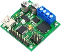
VSA provides speed control for DC motors using the Pololu Jrk. Whereas the other SSC's descried here provide position control, VSA and the Pololu Jrk controller provide speed control. The Jrk communicates with VSA via the USB port and the RAPU via the TTL serial port. When used with VSA, the channel address is the board's ID. The default board ID is 11, so the default address in VSA should also be 11. Use the Pololu configuration utility to set the controller to "USB dual mode."